Merchandise Description
Lifting Products Xihu (West Lake) Dis. Wheel Gadget/ Head Sheave/ Sheave Pulley
Introduction:
Mine hoist can be divided into 2 kinds 1 kind is JKE sequence single rope mining hoist and the other is Multi-rope friction hoist.
This collection mine hoist which includes 2m-5m one tubular and double tubular types, and can be utilized for mining hoist, staff lifting and substance and gear descending from vertical shafts or inclined shafts of coal, metallic and nonmetal ores.
JK mine hoist is mainly used in inclined roadways and wells of coal mines, metal mines and non-metal mines to hoist or lower personnel and materials.
Specialized parameters:
| Model | Drum | Tension PF |
Tension Differe |
Rope Diameter |
Lift height (m) | Max Pace |
Reduce pace ratio |
Motor Pace |
||||||
| Number | Dia | Width | 1-layer | 2-layer | 3-layer |
|||||||||
| m | KN | mm | m | m/s | r/min | |||||||||
| JK-2×1.5/twenty | 1 | 2. | 1.5 | 62 | 24 | 305 | 650 | 1571 | 5.two | 20. | 1000 | |||
| JK-2×1.5/31.5 | 31.five | |||||||||||||
| JK-2×1.8/20 | 1.eighty | 375 | 797 | 1246 | twenty. | |||||||||
| JK-2×1.8/31.5 | 31.5 | |||||||||||||
| JK-2.5×2/20 | 2.five | 2.00 | 83 | 28 | 448 | 945 | 1475 | 5. | 20. | 750 | ||||
| JK-2.5×2/31.five | 31.five | |||||||||||||
| JK-2.5×2.3/20 | 2.thirty | 525 | 1100 | 1712 | 20. | |||||||||
| JK-2.5×2.3/31.5 | 31.5 | |||||||||||||
| JK-3×2.2/20 | 3. | 2.20 | 135 | 36 | 458 | 966 | 1513 | 6. | twenty. | |||||
| 2JK-2×1/eleven.two | two | 2. | 1.00 | 62 | 40 | 24 | 182 | 406 | 652 | 7. | 11.2 | |||
| 2JK-2×1/twenty | twenty. | |||||||||||||
| 2JK-2×1/31.five | 31.5 | |||||||||||||
| 2JK-2×1.25/eleven.two | 1.twenty five | 242 | 528 | 838 | eleven.two | |||||||||
| 2JK-2×1.twenty five/20 | 20. | |||||||||||||
| 2JK-2×1.25/31.5 | 31.five | |||||||||||||
| 2JK-2.5×1.2/11.two | 2.5 | 1.20 | 83 | 65 | 28 | 843 | 8.eight | 11.two | ||||||
| 2JK-2.5×1.2/20 | 20. | |||||||||||||
| 2JK-2.5×1.2/31.5 | 31.five | |||||||||||||
| 2JK-2.5×1.5/eleven.2 | 2.5 | 1.50 | 83 | 65 | 28 | 319 | 685 | 1080 | 8.eight | eleven.two | ||||
| 2JK-2.5×1.5/20 | twenty. | |||||||||||||
| 2JK-2.5×1.5/31.five | 31.5 | |||||||||||||
| 2JK-3×1.5/eleven.two | 3. | 135 | 90 | 36 | 289 | 624 | 994 | 10.5 | 11.two | |||||
| 2JK-3×1.5/twenty | 20. | |||||||||||||
| 2JK-3×1.5/31.5 | 31.five | |||||||||||||
| 2JK-3×1.8/eleven.two | 1.eighty | 362 | 770 | 1217 | 11.two | |||||||||
| 2JK-3×1.8/twenty | twenty. | |||||||||||||
| 2JK-3×1.8/31.5 | 31.5 | |||||||||||||
| 2JK-3.5×1.7/eleven.two | 3.five | 1.70 | 170 | 115 | 40 | 349 | 746 | – | 12.six | eleven.two | ||||
| 2JK-3.5×1.7/twenty | twenty. | |||||||||||||
| 2JK-3.5×2.1/eleven.2 | 2.ten | 450 | 950 | – | 11.2 | |||||||||
| 2JK-3.5×2.1/eleven.two | twenty. | |||||||||||||
| 2JK-4×2.1/10 | 4. | 245 | 160 | 48 | 421 | 891 | – | 12.6 | 10. | 600 | ||||
| 2JK-4×2.1/11.two | eleven.2 | |||||||||||||
| 2JK-4×2.1/twenty | twenty. | |||||||||||||
| 2JK-5×2.3/10 | 5. | 2.30 | 280 | 180 | 52 | 533 | – | – | 12 | 10. | 500 | |||
| 2JK-5×2.3/eleven.2 | ||||||||||||||
|
US $5,000-6,000 / Ton | |
1 Ton (Min. Order) |
###
| Certification: | CE, ISO 9001:2008 |
|---|---|
| Standard: | ASME, BS, ANSI, GB, ASTM, DIN |
| Surface Treatment: | Sand Blast |
| Manufacturing Process: | Forging |
| Material: | Carbon Steel |
| Name: | Head Sheave |
###
| Customization: |
Available
|
|---|
###
| Model | Drum | Tension PF |
Tension Differe |
Rope Diameter |
Lift height (m) | Max Speed |
Reduce speed ratio |
Motor Speed |
||||||
| Number | Dia | Width | 1-layer | 2-layer | 3-layer |
|||||||||
| m | KN | mm | m | m/s | r/min | |||||||||
| JK-2×1.5/20 | 1 | 2.0 | 1.5 | 62 | 24 | 305 | 650 | 1025 | 5.2 | 20.0 | 1000 | |||
| JK-2×1.5/31.5 | 31.5 | |||||||||||||
| JK-2×1.8/20 | 1.80 | 375 | 797 | 1246 | 20.0 | |||||||||
| JK-2×1.8/31.5 | 31.5 | |||||||||||||
| JK-2.5×2/20 | 2.5 | 2.00 | 83 | 28 | 448 | 945 | 1475 | 5.0 | 20.0 | 750 | ||||
| JK-2.5×2/31.5 | 31.5 | |||||||||||||
| JK-2.5×2.3/20 | 2.30 | 525 | 1100 | 1712 | 20.0 | |||||||||
| JK-2.5×2.3/31.5 | 31.5 | |||||||||||||
| JK-3×2.2/20 | 3.0 | 2.20 | 135 | 36 | 458 | 966 | 1513 | 6.0 | 20.0 | |||||
| 2JK-2×1/11.2 | 2 | 2.0 | 1.00 | 62 | 40 | 24 | 182 | 406 | 652 | 7.0 | 11.2 | |||
| 2JK-2×1/20 | 20.0 | |||||||||||||
| 2JK-2×1/31.5 | 31.5 | |||||||||||||
| 2JK-2×1.25/11.2 | 1.25 | 242 | 528 | 838 | 11.2 | |||||||||
| 2JK-2×1.25/20 | 20.0 | |||||||||||||
| 2JK-2×1.25/31.5 | 31.5 | |||||||||||||
| 2JK-2.5×1.2/11.2 | 2.5 | 1.20 | 83 | 65 | 28 | 843 | 8.8 | 11.2 | ||||||
| 2JK-2.5×1.2/20 | 20.0 | |||||||||||||
| 2JK-2.5×1.2/31.5 | 31.5 | |||||||||||||
| 2JK-2.5×1.5/11.2 | 2.5 | 1.50 | 83 | 65 | 28 | 319 | 685 | 1080 | 8.8 | 11.2 | ||||
| 2JK-2.5×1.5/20 | 20.0 | |||||||||||||
| 2JK-2.5×1.5/31.5 | 31.5 | |||||||||||||
| 2JK-3×1.5/11.2 | 3.0 | 135 | 90 | 36 | 289 | 624 | 994 | 10.5 | 11.2 | |||||
| 2JK-3×1.5/20 | 20.0 | |||||||||||||
| 2JK-3×1.5/31.5 | 31.5 | |||||||||||||
| 2JK-3×1.8/11.2 | 1.80 | 362 | 770 | 1217 | 11.2 | |||||||||
| 2JK-3×1.8/20 | 20.0 | |||||||||||||
| 2JK-3×1.8/31.5 | 31.5 | |||||||||||||
| 2JK-3.5×1.7/11.2 | 3.5 | 1.70 | 170 | 115 | 40 | 349 | 746 | – | 12.6 | 11.2 | ||||
| 2JK-3.5×1.7/20 | 20.0 | |||||||||||||
| 2JK-3.5×2.1/11.2 | 2.10 | 450 | 950 | – | 11.2 | |||||||||
| 2JK-3.5×2.1/11.2 | 20.0 | |||||||||||||
| 2JK-4×2.1/10 | 4.0 | 245 | 160 | 48 | 421 | 891 | – | 12.6 | 10.0 | 600 | ||||
| 2JK-4×2.1/11.2 | 11.2 | |||||||||||||
| 2JK-4×2.1/20 | 20.0 | |||||||||||||
| 2JK-5×2.3/10 | 5.0 | 2.30 | 280 | 180 | 52 | 533 | – | – | 12 | 10.0 | 500 | |||
| 2JK-5×2.3/11.2 | ||||||||||||||
|
US $5,000-6,000 / Ton | |
1 Ton (Min. Order) |
###
| Certification: | CE, ISO 9001:2008 |
|---|---|
| Standard: | ASME, BS, ANSI, GB, ASTM, DIN |
| Surface Treatment: | Sand Blast |
| Manufacturing Process: | Forging |
| Material: | Carbon Steel |
| Name: | Head Sheave |
###
| Customization: |
Available
|
|---|
###
| Model | Drum | Tension PF |
Tension Differe |
Rope Diameter |
Lift height (m) | Max Speed |
Reduce speed ratio |
Motor Speed |
||||||
| Number | Dia | Width | 1-layer | 2-layer | 3-layer |
|||||||||
| m | KN | mm | m | m/s | r/min | |||||||||
| JK-2×1.5/20 | 1 | 2.0 | 1.5 | 62 | 24 | 305 | 650 | 1025 | 5.2 | 20.0 | 1000 | |||
| JK-2×1.5/31.5 | 31.5 | |||||||||||||
| JK-2×1.8/20 | 1.80 | 375 | 797 | 1246 | 20.0 | |||||||||
| JK-2×1.8/31.5 | 31.5 | |||||||||||||
| JK-2.5×2/20 | 2.5 | 2.00 | 83 | 28 | 448 | 945 | 1475 | 5.0 | 20.0 | 750 | ||||
| JK-2.5×2/31.5 | 31.5 | |||||||||||||
| JK-2.5×2.3/20 | 2.30 | 525 | 1100 | 1712 | 20.0 | |||||||||
| JK-2.5×2.3/31.5 | 31.5 | |||||||||||||
| JK-3×2.2/20 | 3.0 | 2.20 | 135 | 36 | 458 | 966 | 1513 | 6.0 | 20.0 | |||||
| 2JK-2×1/11.2 | 2 | 2.0 | 1.00 | 62 | 40 | 24 | 182 | 406 | 652 | 7.0 | 11.2 | |||
| 2JK-2×1/20 | 20.0 | |||||||||||||
| 2JK-2×1/31.5 | 31.5 | |||||||||||||
| 2JK-2×1.25/11.2 | 1.25 | 242 | 528 | 838 | 11.2 | |||||||||
| 2JK-2×1.25/20 | 20.0 | |||||||||||||
| 2JK-2×1.25/31.5 | 31.5 | |||||||||||||
| 2JK-2.5×1.2/11.2 | 2.5 | 1.20 | 83 | 65 | 28 | 843 | 8.8 | 11.2 | ||||||
| 2JK-2.5×1.2/20 | 20.0 | |||||||||||||
| 2JK-2.5×1.2/31.5 | 31.5 | |||||||||||||
| 2JK-2.5×1.5/11.2 | 2.5 | 1.50 | 83 | 65 | 28 | 319 | 685 | 1080 | 8.8 | 11.2 | ||||
| 2JK-2.5×1.5/20 | 20.0 | |||||||||||||
| 2JK-2.5×1.5/31.5 | 31.5 | |||||||||||||
| 2JK-3×1.5/11.2 | 3.0 | 135 | 90 | 36 | 289 | 624 | 994 | 10.5 | 11.2 | |||||
| 2JK-3×1.5/20 | 20.0 | |||||||||||||
| 2JK-3×1.5/31.5 | 31.5 | |||||||||||||
| 2JK-3×1.8/11.2 | 1.80 | 362 | 770 | 1217 | 11.2 | |||||||||
| 2JK-3×1.8/20 | 20.0 | |||||||||||||
| 2JK-3×1.8/31.5 | 31.5 | |||||||||||||
| 2JK-3.5×1.7/11.2 | 3.5 | 1.70 | 170 | 115 | 40 | 349 | 746 | – | 12.6 | 11.2 | ||||
| 2JK-3.5×1.7/20 | 20.0 | |||||||||||||
| 2JK-3.5×2.1/11.2 | 2.10 | 450 | 950 | – | 11.2 | |||||||||
| 2JK-3.5×2.1/11.2 | 20.0 | |||||||||||||
| 2JK-4×2.1/10 | 4.0 | 245 | 160 | 48 | 421 | 891 | – | 12.6 | 10.0 | 600 | ||||
| 2JK-4×2.1/11.2 | 11.2 | |||||||||||||
| 2JK-4×2.1/20 | 20.0 | |||||||||||||
| 2JK-5×2.3/10 | 5.0 | 2.30 | 280 | 180 | 52 | 533 | – | – | 12 | 10.0 | 500 | |||
| 2JK-5×2.3/11.2 | ||||||||||||||
How to Assemble a Pulley System
A pulley is a wheel that rotates on a shaft or shaft to support the movement of a taut cable. Pulleys allow power to be transmitted from the shaft to the cable.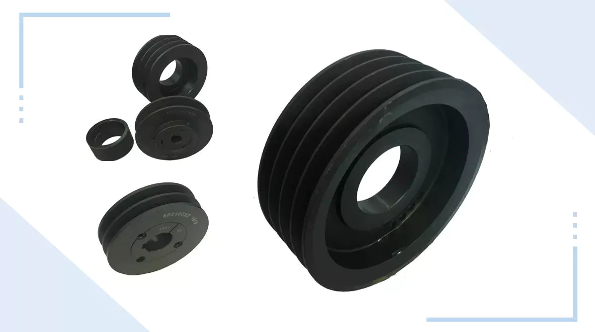
Simple pulley
The simplest theory of operation of a pulley system assumes that the rope and weight are weightless and that the rope and pulley are not stretched. Since the force on the pulley is the same, the force on the pulley shaft must also be zero. Therefore, the force exerted on the pulley shaft is also distributed evenly between the two wires passing through the pulley. The force distribution is shown in Figure 1.
The use of simple pulleys is as old as history. Before the Industrial Revolution, people relied on muscle strength to carry heavy loads. Pulleys, levers and ramps make this possible. Today, we can see pulleys in a variety of systems, from exercise equipment to garage doors, and even rock climbers use them to help them reach greater heights. As you can see, these simple machines have been around for centuries and are used in everyday life.
Another simple pulley system is the pulley system. In this system, there is a fixed pulley at the top and a movable pulley at the bottom. The two pulleys are connected by a rope. This combination reduces the amount of work required to lift the load. Additionally, the ropes used in this system are usually made of rope and woven through the individual wheels of the pulley drum.
A pulley is an ingenious device that distributes weight evenly and can be used to lift heavy objects. It is easy to build and can be easily modified for a wide range of activities. Even young children can make their own with very few materials. You can also use simple household items such as washing machines, thin textbooks and even chopsticks. It’s very useful and can be a great addition to your child’s science and engineering activities.
The simplest pulley system is movable. The axis of the movable pulley can move freely in space. The load is attached to one end of the pulley and the other end to the stationary object. By applying force on the other end of the rope, the load is lifted. The force at the other end of the rope is equal to the force at the free end of the pulley.
Another form of pulley is the compound pulley. Compound pulleys use two or more wheels to transmit force. Compound pulleys have two or more wheels and can lift heavier objects. Dim is POLE2.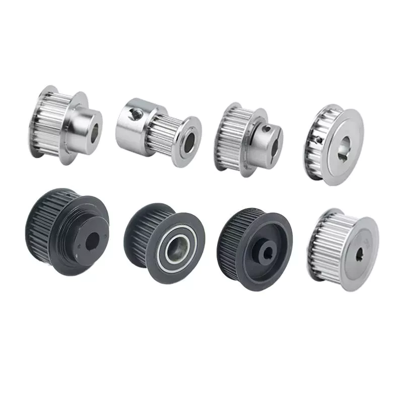
tapered pulley
It is important to clean and align the bolt holes before assembling the tapered pulley. The screws should be lubricated and the threads cleaned before installation. To install the pulley, insert it into the shaft keyway. The keyway should be aligned with the shaft hole to prevent foreign matter from entering the pulley. Then, alternately tighten the bolts until the pulley is tightened to the desired torque.
A tapered pulley is a basic structure. The pulley belt is arranged across four steps. Installed between the headstock casting and the main shaft, it is often used in the paper industry. It integrates with printing machinery and supports assembly lines. These pulleys are also available in metric range options, eliminating the need for ke-waying or re-drilling. They are easy to install, and users can even customize them to suit their needs.
CZPT Private Limited is a company that provides unique products for various industries. This large product is used for many different purposes. Also, it is manufactured for industrial use. The company’s website provides detailed specifications for the product. If you need a tapered pulley, contact a company in your area today to purchase a quality product!
Tapered pulleys are vital to paper mill machinery. Its special design and construction enable it to transmit power from the engine source to the drive components. The advantages of this pulley include low maintenance costs and high mechanical strength. Cone wheel diameters range from 10 inches to 74 inches. These pulleys are commonly used in paper mills as they offer low maintenance, high mechanical strength and low wear.
A tapered sleeve connects the pulley to the shaft and forms an interference fit connector. The taper sleeve is fixed on the shaft with a key, and the corresponding inner hole is fixed on the shaft with a key. These features transmit torque and force to the pulley through friction. This allows the tapered pulley to move in a circular motion. The torque transfer characteristics of this pulley are most effective in high speed applications.
The sleeve is the most important part when assembling the tapered pulley. There is an 8-degree taper inside the cone, which is closely connected to the inner surface of the pulley. Taper sleeves and pulleys are interchangeable. However, tapered pulleys can be damaged after prolonged use.
pulley pulley system
A pulley pulley system is a great way to move heavy objects. These systems have been around for centuries, dating back to the ancient Greeks. This simple mechanism enables a person to lift heavy objects. These blocks are usually made of rope, and the number of turns varies for different types of rope. Some blocks have more cords than others, which creates friction and interferes with the easy movement of the lifting system.
When using a pulley pulley, the first thing to decide is which direction to pull. Unfavorable rigging means pulling in the opposite direction. In theory, this method is less efficient, but sometimes requires a certain amount of work space. The benefit is that you will increase the mechanical advantage of the pulley by pulling in the opposite direction. So the interception and tackle system will give you more of a mechanical advantage.
Pulley pulleys are an excellent choice for lifting heavy objects. The system is simple to install and users can easily lift objects without extensive training. Figure 3.40 shows a pulley in action. In this photo, the person on the left is pulling a rope and tying the end of the rope to a weight. When the rope is attached to the load, the rope will be pulled over the pulley and pulley.
The blocks on the blocks are attached to the ends of the rope. This creates unique lifting advantages compared to single-line systems. In Figure 3, the tension of each thread is equal to one-third of the unit weight. When the rope is pulled over the pulley, the force is divided equally between the two wires. The other pulley reverses the direction of the force, but that doesn’t add any advantage.
Use pulleys to reduce traction and load. The weight of the load has not changed, but the length of the rope has increased. Using this method, lifting the load by pulling the rope four times reduces the force required to lift one foot. Likewise, if the pulley system had four pulleys instead of three, the length of the rope would be tripled.
The system can transmit loads in any direction. Rope length is determined by multiplying the distance from the fixed block to the load by the mechanical advantage. If the mechanical advantage is 3:1, then passing the rope through the pulley 3 times will produce the required traction distance. Also, the length of the rope will depend on the mechanical advantage, so if the load is three times the length of the rope, it will be more than three times the required length.


editor by czh 2022-12-02